C-Insight User Manuals
CityMIND
Operator Handbook
This document contains proprietary information, which is the sole property of CityShob Software Ltd. The document is submitted to the recipient for their use only. By receiving this document, the recipient undertakes not to duplicate the document or to disclose in part of, or the whole of, any of the information contained herein to any third party without prior written permission from CityShob Software Ltd.
Table of Contents
3.4. Multi Language Support 13
5.1. Handling Automatic Events 30
5.2. Creating Manual Events 45
5.3. Editing an Existing Event 49
5.5. Share – Delegating an Event 55
CHAPTER 7. Additional Features 91
7.1. Managing Pages & Tours 91
7.5. Finding Location of Event or Camera 108
7.7. Show Covering Sensors 112
7.8. Showing Video from Camera on Map 113
7.13. Instant Messaging (IM) 121
CHAPTER 8. Suspicious Activity 133
8.1. Suspicious Vehicle Indicators 134
8.2. Appearance and Behavior Indicators 135
8.3. Suspicious Object Indicators 138
9.1. About the CityMind Mobile Application 139
9.2. Log into and Out of C-React 140
9.3. Create an Event (Report) 142
9.4. Initiate a Vehicle Investigation 144
9.5. Initiate a Suspect Investigation 147
10.2. Investigation Enrichment 148
Operators are responsible for monitoring live activities, performing routine and special tasks, and handling automatic and manual events.
Each operator is assigned zones from the Shift Manager. During the shift, the operator monitors the zones including handling events and tasks that take place in that zone. The Operator is also responsible to notice suspicious activity that he sees during his shift, creating events and reporting on this activity.
If the operator identifies suspicious activity, he starts performing a defined procedure for the specific situation he is monitoring. He also reports it to the Shift Manager and becomes responsible for handling the resulting event if necessary, which may include monitoring the relevant videos, tracking suspects, directing emergency forces, and creating relevant objects in the system.
The operator is responsible for filling out the event details in the event kit, and if necessary, request an in-depth investigation of events from the investigator.
This section lists the tasks and activities that the Operator is required to perform during the shift.
Before Shift:
- Incoming Shift Manager briefs shift personnel: Operators, Investigators, and Administrator
Shift Start:
- Log on to Windows and open the CityMIND system
- Switch to assigned Zones
- Automatically receive the Tasks and Events that are located in the assigned Zones.
- Receive tasks from Shift Manager (may include routine Tasks and Tasks from external organizations)
During Shift:
- Handle live Events
- Handle Tasks
- Routine monitoring:
- Report unusual or suspicious activities
- Create Manual Events when needed
- Group related Events
Shift End:
- Send report to Shift Manager
- Close CityMIND and log off Windows
- Shift Manager debriefs the shift personnel
The CityMIND user interface is divided into three screens: Data, Video and Unified Situation Awareness Picture (USAP).
- Data screen displays information on Events, Tasks, objects, and also information related to Shift Management and Administration.
- Video screen displays video from cameras – both live and playback, and is used for performing actions that require information from cameras.
- USAP screen shows a 2D and 3D representation of the monitored urban environment.
Each screen contains a ribbon that is divided into tabs, sub-tabs, groups, and drop-down lists.
Figure 1. CityMIND User Interface
Figure 2. Data Screen and Panes
The Data screen is used for handling Events, Tasks and Objects. It is also used for management and administration tasks. The interface comprises the following elements:
- Tabs: The tabs show information in major categories. The Operator can access the Events and Suspects tabs.
- Drop-Down List: The drop-down list shows information specific to the selected tab, such as People and Red List vehicles under Suspects.
- Sub-Tabs: Each sub-tab contains a Tool Ribbon for handling a different aspect of the Data screen.
- Tool Ribbon: The tool ribbon shows command icons for actions that can be performed on selected items.
- Lists Pane: The Lists pane is used with suspicious people and vehicles, and shows lists and groups of lists for these object types.
- Items Grid: The Items Grid lists items in a grid format. These can be Events and Tasks, but also Search results, and Objects belonging to a list.
- Information Pane: The information pane shows the basic information related to the item selected in the Items Grid. The pane is sectioned and the information it shows varies according to the item selected, such as
- Picture of the selected item, if applicable
- Demographic Information on the item
- Description of the item
- Related Items, such as people, vehicles sites and administrative information related to events and tasks. These items can be linked to other items, and their relationship chart can be displayed
Figure 3. Video Screen and Panes
The Video screen is used for monitoring live and recorded video from the cameras deployed throughout the urban environment in strategic locations. It can be used for performing actions related to the cameras, such as taking snapshots, creating bookmarks, and face capturing and face recognition.
The screen comprises the following elements:
- Tabs: Tabs show pages of tile layouts, which may be associated with new, or previously saved, events or tasks. The layouts can also display cameras in synchronized playback, or be used to show sensors coverage. The Operator can open new pages (tabs), each one configured to show a specified layout and set of cameras.
- Sub-Tabs: Each sub-tab contains a Tool Ribbon for handling a different aspect of the Video screen.
- Tool Ribbon: The Tool Ribbon shows command icons for actions that can be performed on selected tiles.
- Camera List: The Camera list shows all the cameras in the organization. Above the list is a camera search field. Entering part of the camera name filters the list according to the search criteria.
- Video Tiles: The video tiles show the recorded or live video streams from the selected cameras. The tile layout can be customized, but by default there are four tiles per tab.
- Timeline: The timeline shows the time frame for the selected video playback. It can be used to control the speed of the playback, bookmark specific moments, and extract photos to be saved for later use.
Figure 4. USAP Screen and Panes
The USAP screen shows a 2D and 3D representation of the monitored urban environment, including models of important buildings and structures. The screen displays an aerial photograph map of the urban environment, which contains an overlay of Zone borders, special sites, locations of Events, Tasks, sensors, and sensors’ fields of view.
The USAP window comprises the following elements:
- Tab: By default there is only one tab on the USAP screen.
- Sub-tabs: Each Sub-tab includes a tool ribbon for handling a different aspect of the USAP screen.
- Tool Ribbon: The tool ribbon shows command icons for which the operator has permission.
- Layers: these include all defined layers, divided into groups.
- GIS Layers: Map layers of imported information and models, such as roads, buildings, bridges, and other points of interest
- System Layers: Geographic location of the objects that are defined in the system, such as zones, sites, event and task locations, cameras organized into static and dynamic layers.
- My Layers: Logged Operator’s defined entities, such as selected sensors and other important entities that the Operator located on the map.
- Sensors: The Sensors pane lists the sites, streets, junctions and zones where sensors are located.
- Data Grid: The Data Grid lists all the entities in the layer or zone that is selected in the Public Layers pane or the Sensors pane. This includes basic information on each entity, and applies also to sites streets and junctions.
- 2D/3D Map: This is a visual representation of the urban environment with all the system entities, elements and layers.
- Compass: The Compass shows the compass direction to which the 3D view is facing. The display can be adjusted through the compass.
- Orientation Map: The Orientation map is a miniature 2d map of the urban area with the currently displayed zone highlighted.
- Locate On Map: The Locate On Map function allows operators to search for locations or entities on the map. The search results appear as hyperlinks, which when clicked will center on the location on the map.
You can choose the language in which the screen text is displayed.
Note: You must have permissions to change the language.
To select the interface language:
- From any of the tabs, in the Home sub-menu, from the Select Language drop-down list, choose the language of your choice.
Figure 5. Select Language Drop-down Menu
- You’ll be prompted that the application language is about to change. You’ll be requested to confirm the change.
Figure 7. Confirm Language Selection
- Upon confirmation, the application will restart. Your choice will be saved for the next time you log in.
The CityMIND Operator is assigned tasks by his Shift Manager, or he can create tasks for himself. The tasks commonly require the Operator to monitor various cameras and sensors for critical information, and then report the findings to the Shift Manager.
There are two types of tasks: patrol and general.
Patrol tasks require the Operator to monitor a tour, which is a sequence of cameras along a designated route or path.
General tasks are all other tasks, such as monitoring specific sites during specific hours.
The Shift Manager can create both General and Patrol tasks and assign them to any Operator. The Operator can also create both task types for himself.
All tasks are displayed in the Tasks grid in the data screen.
The options to display Tasks in the grid are the same as those in the Events grid.
The Tasks Grid displays the following information about each task: ID, Priority, Recurring, Task type (general or patrol), State, Task Name, Zone, Assign to, Owner, Start Time, and Due time.
The grid can be sorted and filtered according to this information.
One of The Operator’s primary responsibilities is to perform the tasks that the Shift Manager assigned to him. The following procedure explains how to handle and close a task.
To handle an assigned task perform the following:
- By default, the tasks tab is opened in Data screen when log in to the system.
Figure 8. Launch the Task Grid
- In the Tasks tab, select the Tasks in the sub-tab.
Figure 9. Data Screen Tasks Grid
Note: Clicking the Priority column header lists the tasks according to task priority.
Clicking Start Time lists the tasks chronologically, showing the next upcoming tasks at the top of the list.
- Double-click a task in the grid to open the task kit in a new window.
Note: In the Task grid, you can view the Task’s details by selecting it. The details appear in the right-hand pane.
Figure 10. Task Details Pane
- In the upper-right area of the pane, follow the task instructions.
Task instructions commonly require the Operator to view the video streams, spot suspicious vehicles or people, or create an event. The following steps describe the actions commonly required to perform a task.
- Note any important, suspicious, or noticeable events that were viewed in the cameras and bookmark the live or recorded video when the event occurred.
- Click the Edit Task Definition icon ().
The task kit can now be edited.
- To add a written report, in the lower-right area of the pane, click the New Report () icon.
- In the text box in the Reports tab, enter the important information into the report.
- Click Save and Close to save the report and close the task.
When an Operator is told by the Shift Manager to perform an action, he can create a task for himself.
There are two major task types: General and Patrol. Creating a Patrol task requires selecting a sequence of cameras, a camera tour, which is attached to the task. The cameras in both General and Patrol tasks open automatically when the task is accepted and initiated.
A General task may be any required activity that is scheduled, such as monitoring a site.
In addition, there are several weather tasks, including: Rain, Snow, Storm, Sandstorm, Fog, Slippery surface and Hail.
To create a new task, perform the following:
- In the Data screen, select the Tasks tab, and then the Tasks sub-tab, click the Create Task
() icon, and choose the relevant type.
Figure 11. Tasks Tab Command Ribbon
Or, in the USAP screen, right-click on the map, select New Task from the drop-down list and select the task type: General, Patrol or any other from the drop-down list.
Or, in the Home sub-tab in any window, click New Item and select New Task from the drop-down list; then s elect the task type.
A New Task window is displayed.
Figure 12. New Task Properties Pane
- In the Properties pane, enter the Name and select a Priority.
- Start Time and Due Time: By default, the start time is one hour after the task was created, and due time is one hour after the start time. You can change these as desired.
- If the task is a recurring one, click Select.
The following window is displayed:
Figure 13. Recurring Tasks Dialog Box
- In the Activity time area, select the time of day the task Starts, the task Ends, and its Duration.
- Select one of the Recurrence pattern radio buttons (weekly, monthly and yearly), and select or enter the appropriate information.
- Days for weekly recurrences
- Date in the calendar for monthly recurrences
- Date (in mm/dd format) for yearly recurrences
- In the Range of recurrence area, enter the Start date − when the task is first performed.
The current date is the default date. Enter a different date to begin performing the task in the future.
- If you want to set the recurring task to end by a specific date, select the End by radio button and enter the date when the task is finished.
- To save the task recurrence settings, click OK.
- In the Instructions pane, enter instructions for the actions that are to be performed in the task.
Figure 14. Task Instructions Pane
- In the Task Details, select the relevant locations associated with the task.
- Select the locations associated with the task by clicking the Add Location icon (). A row appears with the map coordinates.
- Click the thumbtack icon ().
A drop-down list of location types appears.
Figure 15. Method for Selecting Location
- Select how to define the location:
- Coordinates: Click a location on the USAP map or enter the exact coordinates in the fields
- Polygon: Draw a polygon on the USAP map to define the area.
- Placemark: Create a placemark on the map.
- Site: Select a site from a list of existing sites on the map.
- Zone: Select a zone from the list of zones.
- Select the cameras that are used in the task by clicking the Add Camera icon ().
The Camera Search dialog box appears, listing all the configured cameras by Zones, Sites, Streets and Junctions.
Figure 16. Camera Search Dialog Box
- Along the left edge of the dialog box, click the plus (+) sign to the left of the Zones, Sites, Streets and Junctions to expand the lists of these areas.
- Select the cameras to perform the task:
- One by one, select a camera from the list, and click the right arrow (►), or double-click it, to add it to the Cameras to display list on the right.
- Or, select more than one camera by pressing Shift when selecting each camera, and then clicking the right arrow (►) to add all the selected cameras to the Cameras to display list on the right.
- Click Select.
- Review all the task details on the screen, and then click Save and Close () to save the task.
Figure 17. New Defined Task
Events are generated automatically by the system, or created manually by a CityMIND Operator. Automatic events are generated from predefined rules, defined by the Shift Manager or Administrator in the Rule Based Engine (RBE). These detections can be extracted from any of the system sensors like the following: analytics cameras that identify certain behavior of people or vehicles, such as crowding, loitering, crossing a line; License Plate Recognition (LPR) lane units that identify the license plates of suspicious vehicles; Tamper detectors that identify attempts to tamper with the cabinets or the camera poles; Gunshot detection audio analytics, Face recognition etc.. The automatic event type, severity, and priority are determined according to the rule assigned to that event. Manual events are created by the Operator.
CityMIND creates automatic events when the system detects a situation that matches a defined rule. They initially appear as popups on all the screens, where the operator can accept them − these are also added to the events grid. If the operator does not accept an event, he can later access it from the grid and open it from there.
Operators can also create events manually, when they observe suspicious behavior while monitoring an area.
Events can also be grouped together. If there are several related events, or events that are part of a series of ongoing events, then the operator will want to group these events together.
Events can be assigned to multiple operators − but only one operator can own an event. For example, if multiple operators are assigned to a zone, each of the operators receives notifications on automatic events that are located inside the zone, but only one operator can accept an Event and own it. This operator is the only one who can edit that event. Manual events are owned by the operator who created them. If necessary, the Shift Manager can shift the event ownership to another operator.
Up to 1000 recent events can be displayed on the Events grid in the Data screen.
Figure 18. Events Grid
As events are created, processed and closed, the State column is updated to show the current event status, as follows:
Table 1. Event States
|
Event State |
Description |
|
Unhandled |
Event created but not assigned to a specific operator |
|
Assigned |
Event created and assigned to a specific operator who has not yet handled it |
|
In Process |
Event handle by an operator |
|
Closed |
Operator handled and closed the event. Such an event is not listed in the All Open Events |
The grid can be sorted and filtered according to this information.
Selecting an event in the Events grid shows its details in the lower pane.
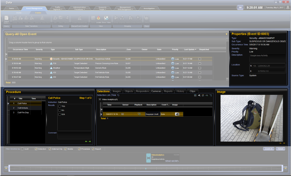
This section explains how to handle Automatic Events. Automatic Events initially appear as popups on all the screens, but can also be accessed from the Event Grid.
To Handle an Automatic Event, perform the following:
- Click Handle on the popup alert that appears on the data screen.
Note: The pop up alert disappears after 20 seconds, but the Event is still added to the Events grid. See section 5.3 to learn how to open and edit an Event.
The Event Kit opens, and the Event status automatically changes to In Process.
Figure 20. Automatic Event Kit
The video from the applicable cameras is displayed on the Video screen – up to three cameras can be viewed along- side the playback, to form a maximum of six tiles.
The USAP window shows the Event location at the center of the view window.
- If you determine that the Event is a false alarm, then in the Actions section of the Events tab, click the Close as False Alarm icon ().
The event is closed as a false alarm.
- If you determine that the event is a real event, continue to the next step.
- Follow the steps in the procedure grid.
Figure 21. Event Kit
Note: Use the left or right arrows () to navigate between the steps.
- If relevant add the following:
- Objects: In the bottom, center section of the Objects tab, see Adding Objects. Other system objects, such as people, vehicles and sites can be attached to the event.
- Cameras, Video clips: In these tabs, see Adding Cameras and Video Clips buttons to add Recorded video streams from the detecting or other cameras can be added to the event.
- Images: In this tab see Adding Snapshots button to add snapshots from the detecting camera or other cameras can be added to the event.
- After completing the Event procedure, and determining the severity of the Event, fill in a report:
Figure 22. New Report
- At the lower-right area of the pane, click the New Report () icon.
- Enter the report into the text box in the Reports tab.
- Click Create Report.
- Close the Event, by performing one of the following:
- Save and Close: Closes the kit with the intention of coming back to it later. Event status remains Open.
- Close Kit: Closes the Event kit without saving any changes or completing its procedure.
- Close Event: Closes the Event, because you have completed handling it. Event status changes to Closed.
- Close as False Alarm: Closes the Event as a false alarm.
Note: You can revisit this Event again from the Events grid for future updates, see section 5.3, on page 49.
This section explains how to add video cameras and video clips to an Event. You can add video clips from cameras within the system, or external video clips, imported from other people or organizations.
Note: These procedures require you to be the owner of the event.
- Adding a video clip enables you to view a specific footage
- Adding a camera enables you to view on demand – from the resulting link – any of the images created by that camera
- Adding Cameras and Video Clips from Internal Source
To add Cameras to event perform the following:
Figure 23. Video Streams
- In the Event Details section under Camera tab, click the Add Camera () icon.
The Camera Search dialog box appears.
Figure 24. Camera Search Dialog Box
- Along the left edge of the dialog box, click the plus (+) sign to expand the list of any of the following parameters: Zones, Sites, and Streets.
- Select a camera from the list.
Note: You can select multiple cameras by holding down the CTRL or SHIFT keys while selecting.
- Click the right arrow (►) to add the selected cameras to the Cameras to display list in the right-hand pane.
- In the Time Definitions section, select whether you want to add the camera’s live streams, playback by time video clip, or playback by bookmark video clip to the event kit.
Note: If you select Playback, you also need to enter the date and time for the playback range. If you select Bookmark, you need to choose a bookmark from the list of saved bookmarks.
- If you want to select additional cameras with different time definitions, repeat steps 3-5 until you have selected all the relevant cameras.
- Click Select.
The selected cameras are added to the Event kit.
- To save the changes you made to the event, click Save and Close or Save.
- Adding Video Clips from External Source
To add a video clip from an external source performs the following:
- In the Event Details section of the Events tab, under External Clips, click the Add Clip () icon.
The Clip Search dialog box appears.
Figure 25. External Clip Tab
- Select a video clip from the file system and click Open. The video clip will be uploaded, and will appear in the External clips list.
Note: Supported file types are *.avi and *.mp4.
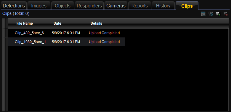
Figure 26. Import External Clip Search
- Save the event.
This section explains how to add objects to an Event kit. You can add objects (suspected people or vehicles, as well as sites) to an Event.
To add an object to an Event, perform the following:
Figure 27. Event Kit – Objects
- In an open Event kit, that you are editing, in the bottom right corner in the Objects tab, click the Add objects icon:
The Advanced Search dialog box appears.
Note: You can also create and add Suspects and Vehicles and add them to the event, by clicking the Create Suspects ![]() and Create Vehicles
and Create Vehicles ![]() icons. For more information, see the CHAPTER 6, page 58.
icons. For more information, see the CHAPTER 6, page 58.
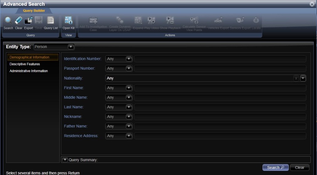
Figure 28. Advanced Search Dialog Box – Person
- In the Entity Type drop-down list, select either Person or Vehicle.
The relevant search criteria appear in the grid.
- Enter search criteria, and in the Query Builder tab of the Query section, click Search.
The results are displayed in the results grid (see example below).
Figure 29. Advanced Search Dialog Box – Results
- In the results grid, select the objects you want to add.
Note: You can select multiple objects by holding down the CTRL or SHIFT keys while selecting.
- If you want to add an object to the Event, in the Query Builder tab of the Query section, click Save.
Note: The Query Builder allows you to search for any object in the system. You can access it in the Home sub-tab with the Search icon.
Note: You can later remove the object, by clicking the Remove Object icon.
This section explains how to add snapshots to an event. To create a snapshot, see section 7.4 on page 107.
To add a Snapshot to an Event, perform the following:
Figure 30. Event Kit – Event Image
- In the Images tab section of the Event that you are editing, choose Add image.
An Open File dialog box appears.
- Browse to the file you want to add, select it, and click Open.
- To save the changes you made to the Event, on the Events tab; then, click Save and Close.
Operators can create manual events for further investigations in several occasions: When observing suspicious activity while performing routine tasks, when suspecting malicious activity in a specific location, when watching an activity on the video screen, and more. Therefore CityMIND supports several ways of creating manual events.
You can create events from:
- The Events tab in the ribbon
- From the USAP screen, pointing to specific coordinates
- From the Video screen tile
Manual Events include the same type of information as Automatic Events, but the operator enters all the information manually.
This section explains the full menu and process of the manual event creation.
Event creation from USAP screen and from the Video screen, is similar to the process described below, with the addition of predefined data. For example: when starting the creation of manual events from the USAP screen, the coordinates will be already given. The full description for these cases is available in the related sections.
To Create a New Event, from the Ribbon, perform the following:
- In the Events tab of the Data screen, select the Home sub-tab; then, in the New group, click Event.
Or, in any screen in the Home tab, click the New Item icon
() and select Event () from the drop-down list.
An Event Kit opens.
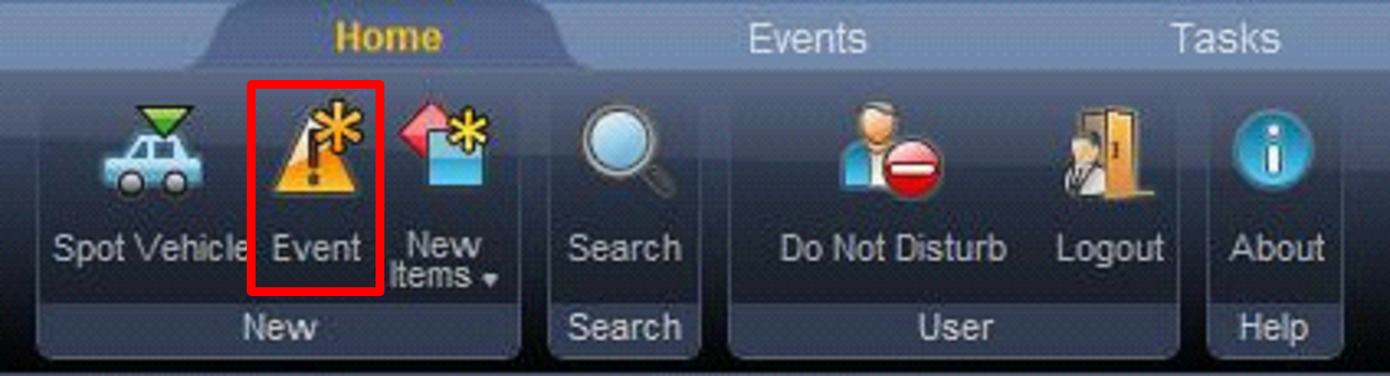
Figure 31. Create Manual Event
- In the Properties Pane, enter the following information:
Table 2. Manual Event Properties
|
Field |
Description |
|
Start Time |
The date and time when the Event took place. This information is automatically inserted when the Event is created, but you can edit it. |
|
Type |
The Event type |
|
Sub Type |
The Event subtype |
|
Severity |
The severity of the Event |
|
Priority |
The Event priority |
- In the Event details pane, enter the following information:
- Description: Type a description of the Event.
- Location: Either manually enter the coordinates of the Event location
Or, click the icon; then, click a location on the USAP map.
The coordinates are automatically entered.
Figure 33. Add Location from List Dialog Box
Note: If the Event was created directly from the map, the coordinates are entered automatically.
- Follow steps 4-6 in section 5.1.
You can edit existing events. You may need to complete an event that is in process, or update an event upon further investigation.
You can only edit events that you created, were assigned to you by the Shift Manager, or automatic events that you handled. You can also edit an unhandled event by handling it and taking ownership. To handle an event, right-click that Event in the Events grid; then, from the drop-down list select Handle.
To edit an Event, perform the following:
- In the Events grid of the Data screen, select the Event to Edit.
- Click the handle icon ().
- Click the Edit Event icon ().
You can now edit the event.
Note: Clicking the Sync button opens the Event videos in the Video screen and centering on the event location in the USAP.
- When you have completed editing the Event, close the Event using one of the following functions:
- Save and Close: Close the Event with the intention of coming back to it later.
- Close Event: You have completed handling the Event.
- Close as False Alarm: Close the Event as a false alarm.
When you have an aggregation of Events that share common factors, or when multiple Events are created in relation to a single vehicle/person, it is advisable to group these Events as a single Event group.
Grouping Events creates a single overall Event Group to which the individual Events are attached. You can add or remove individual Events, or ungroup the Events entirely.
For example, if you open a car theft Event, and then open another break-in Event involving the same suspect, these Events can and should be combined into a single criminal Event.
Another example would be multiple car accidents due to road damage. Each accident would be a single event, but because they are all related to the same cause, you may want to group them as a single Event.
To Group Events, perform the following:
Figure 34. Group Events
- In the Data screen, in the Event grid, select the Events you want to group, by using the CTRL or SHIFT key
- Click the Group icon ().
Or, right-click and select Group from the drop-down list.
An Event kit opens showing the Father Event for the new Event Group. The member events in the group are called Children Events. Treat the Event Group as a manual Event, and follow the procedure in section 5.2, page 45.
Note: Some of the Father Event fields are filled automatically (start time) from information in the children events.
After the Event Group is created, it appears in the Event Grid with a + sign next to it.
Figure 35. Event Group
Note: You can expand an Events Group to show its attached Events.
To Ungroup an Event Group, perform the following:
- Select the Event Group, and click the Ungroup icon ().
Or right-click the event group and select Ungroup from the drop-down list.
To Add an Event to a Group, perform the following:
Figure 36. Add to Group
- Select the Event, and click the Add to Group icon ().
Or right-click the event group, and select Add to Group from the drop-down list.
A dialog box appears, listing all the Event Groups.
Figure 37. Add to Group
- Select the Event Group you want to add the Event to, and click Select Group.
To Detach an Event from a Group:
Figure 38. Event Group
- Select the Event in the group, and click the Detach icon ().
Or right-click the event group and select Detach from the drop-down list.
CityMIND supports the concept of users belonging to different organizations which use the system concurrently and independently from each other. While users of different organizations share the same infrastructure, the system keeps their data compartmentalized.
In other words, the tenancy is fully kept: Users of one organization have no access at all to data of another organization.
In certain occasions though, different organizations, may want to delegate events from one to another, depending on relevancy. For example, the police may consider an event rather belonging to the fire department. While basically maintaining the privacy of their data, one organization can delegate a specific event to another organization. In this case, the event is closed in the original organization and is created, with its full data from sensors in the new organization.
Once the event is delegated, a new ID is created for it in the system, and the other organization can proceed with handling it. If you re-open the event, these events run in the system as two separate events, handled by two separate organization. Any connection between the events does not exist.
Note: this option is only available permissions were granted for you.
To delegate an event, perform the following:
- In the Events grid, select the Event.
- In the Events area of the tool ribbon, click the Share icon, or right-click the event; then, from the drop-down list select Share.
Figure 39. Share – Delegating an Events
- From the list that opens, select the organization to with which you wish to share the event. You can share with one organization only. Upon sharing, the event will be closed at your events list.
Figure 40. Share – Select Organization
CityMIND relates objects to the activity that occurs in the urban environment. Objects are Sites, Placemarks, People and Vehicles. Operators monitor the activity of suspicious people and vehicles throughout the urban environment, along with the general activity around specified sites. The activity of these suspicious people and vehicles can lead to the triggering of automatic events, and operators may receive tasks to monitor them, which may lead to the creation of manual events.
CityMIND is a powerful geographical system that can link many of the components: Events, Tasks, People and Cameras to specific sites and locations. A site can be a mall, a bank, a hotel, a public building or any other location of strategic importance that needs to be monitored.
The CityMIND Operator handles tasks and events that monitor individual sites or groups of sites. Operators are required to define the sites, once they receive the system for the first time. Once a site is created it remains public until it is deleted.
This section describes how to create a site, associate objects with the site, and explains how the site links to Events.
To create a Site, perform the following:
- In the USAP screen, right-click the map and select Create Site.
Note: Sites can also be created from the Home tab, through the New Items drop-down list.
The New Site dialog box opens, showing all the relevant information.
Figure 41. New Site Dialog Box
- Enter the following information into the relevant fields:
Table 3. New Site Dialog Box Fields
|
Field |
Description |
|
Pictures |
If a picture of the site is available, click the Add Picture icon () and browse to the picture file to open. |
|
Name |
Enter a name to the site. |
|
Type |
Click the drop-down list and select the site type. |
|
Sub-Type |
Click the drop-down list and select the site’s sub-type. |
|
Usage |
Click the drop-down list and select the site’s usage. |
|
Number of Floors |
If the site is a building, enter the number of floors in the building. |
|
Location |
Click the drop-down list and select how to define the site location:
|
|
Additional Identifiers |
Enter free text that describes the site. |
|
Internal Areas |
Define internal areas in the site. |
|
Related Objects |
Add related people to the site. |
- Click the Save and Close icon () to save the new site and close the dialog box.
To edit a site, perform the following:
- Open the site kit, by double-clicking it:
- From an Event kit (see section 5.3, page 49).
- Through an Advanced Search (see section 5.1.2, page 40).
The Site Details window opens.
- Make the required changes to the site, as described, and click the Save and Close icon ().
In order to fulfill your duties, you may need to refer to an intersection as an entity, for example, to view an intersection on the map, or find all cameras that overlook the intersection. CityMIND regards intersections as Sites.
Similarly, you first create a list, and then add intersections to it.
Note: you can use an existing list of sites and add the intersections to it.
To add an intersection list, perform the following:
- In the Data screen, click the Administration tab.
- From the drop-down list, select Locations.
- In the Sites Lists pane along the left edge of the window, click the Plus (+) sign next to All Lists.
- Click the Add New List () icon in the upper-right corner of the pane.
OR
Figure 42. Site Lists Pane
In the tool ribbon, click the Add icon ().
The Create List dialog box appears.
Figure 43. Create List Dialog Box
- Enter the relevant information for the list:
- In the Name field, type a name for the list.
- In the Description field, type a relevant description for the list.
- Click the Save and Close icon () to save the new list.
To create an intersection:
- In the Administration tab, select Locations from the drop-down list.
- In the Sites sub-tab, click the New Site ().
The New Site kit opens.
Figure 44. New Intersection Kit
- Enter the following information into the relevant fields:
Table 4. New Intersection Dialog Box Fields
|
Field |
Description |
|
Site List |
If you did not select a list first, select from the drop-down list, the list where you want to add the site. |
|
Pictures |
If a picture of the site is available, click the Add Picture icon () and browse to the picture file to add. |
|
Name |
Mandatory field. Give a name to the site. |
|
Type |
Mandatory field. From the drop-down list, select Roads. |
|
Sub-Type |
Mandatory field. From the drop-down list, select Intersection. |
|
Location |
From the drop-down list, select how the site location is defined Polygon: Draw the outline of a polygon on the USAP map, see section 6.6 , page 90. |
|
Cameras |
Upon entering location, the camera list is automatically updated with the cameras relevant for the location. This list is updated if the location is updated. |
- Click the Save and Close icon () to save the new site and close the dialog box.
- Viewing Intersection Cameras and Videos
You can view live and playback of cameras related to a specific intersection.
To view camera video of an intersection, perform the following:
- In the Data screen, click the Administration tab.
- From the drop-down list, select Locations.
- In the Sites Lists pane along the left edge of the window, click the Plus (+) sign next to All Lists.
- Choose the intersection you want to view.
- From the Object ribbon, choose Expand to see live cameras in the video and USAP screens, or choose Expand At to see playback mode.
Figure 45. Expand Intersection Cameras
The video screen displays live videos form cameras related to the selected intersection.
Figure 46. Expanding Intersection Cameras – Video
The USAP screen shows the FOV of all related cameras.
Figure 47. Expanding Intersection Cameras – USAP
If you chose Expand At, the following screen appears:
Figure 48. Expand Intersection in Playback Mode
- Fill in the desired date and time parameters for the playback, and then choose Show or Show Synchronized.
The video screen and USAP screen display the desired video playback.
Suspects are people of interest that are defined as such, in the CityMIND system. Suspects may be criminals or terrorists. Suspects can be linked to other objects, sites or vehicles, and to events.
Figure 49. Suspected Person
Operators are also expected to create events if they observe suspected people while monitoring live video. They are expected to create the event and relate the suspect to it − if necessary creating and adding the suspect in the system.
- Defining a Suspect
To define a suspect, perform the following:
- In the video screen, select a tile with Video, select Tile sub-tab and click Snapshot 🡺 Create Suspect Person.
Figure 50. Create Suspected Person
Note: The image of the new person object is taken as a snapshot of the video in the tile. This image may be of low quality and therefore may not suffice for enrollment.
Note: A person can also be created from the Suspect tab 🡺 People drop-down list 🡺 People sub-tab 🡺 New Suspect icon,
Or, from the Home tab, under New Items. Make sure that a suspect list is already created.
The New Person dialog box opens, showing all the relevant information.
Figure 51. New Person Dialog Box
- Enter the following information into the relevant fields:
Table 5. New Person Dialog Box Fields
|
Field |
Details |
|
Pictures |
If a picture of the person is available, click the Add Picture icon () and browse to the picture file. |
|
Picture quality indication |
The top left corner may display a star. The star indicates that this image is the main image for the suspect. If the suspect has multiple images, the main image appears at the suspect grid. The right top corner of the image may contain one of the following indicators:
|
|
Picture quality feedback |
When mouse hovering over the picture quality indicator, a message addresssing image qulity will appear, indicating what can be done to improve piscture quality. This feedback appers both in cases when the image is not good enough for recognition, and also in cases where the quality suffices but can be improved. |
|
Main Picture selection |
CityMIND can be configured to show one of the pictures of a suspect as the main picture. The main picture is the one that displays whenever the suspect is addressed in the system, for example, when an event occurs and the suspect is identified. The first picture of a suspect is automatically selected as its main picture. A Yellow star at the top left corner of the picture indicates that this picture is considered main. You can select a picture to serve as the main picture from the right-click menu. |
|
Demographic Information |
|
|
Identification Number |
Enter the person’s identification number. |
|
Nationality |
Click the drop-down list, and select the person’s nationality. |
|
Passport Number |
Enter the person’s passport number. |
|
First Name |
Enter the person’s first name (given name). |
|
Middle Name |
Enter the person’s middle name. |
|
Last Name |
Enter the person’s last name (family name). |
|
Nickname |
If the person has a nickname or an alias, enter that name here. |
|
Father’s Name |
Enter the name of the person’s father. |
|
Residence Address |
Enter the person’s known residence address. |
|
Descriptive Features |
|
|
Gender |
Click the drop-down list and select if the person is Male or Female. |
|
Eye Color |
Click the drop-down list and select the color of the person’s eyes. |
|
Hair Color |
Click the drop-down list and select the color of the person’s hair. |
|
Height |
Enter the person’s height. |
|
Weight |
Enter the person’s weight. |
|
Complexion |
Click the drop-down list and select the color of the person’s complexion. |
|
Additional Identifiers |
Enter free text of physical information that may assist in identifying the person. |
|
Tracking Information |
|
|
Phone Numbers |
Add the telephone numbers by which the person may be contacted |
|
Related Objects |
Add related objects to the person. |
|
Additional Information |
Enter free text of tracking information that may assist in finding the person. This should not be the same Site and Vehicle information that is related to the person. |
- Click the Save and Close icon () to save the new person and close the dialog box.
If a suspect with the same image already exists, you will be prompted about the duplication. The new suspect will not be saved.
Note: You also have the option of actively searching for the person. For more information, see page 116.
To edit a person, perform the following:
- Click the Suspects tab; then, from the drop-down list select People.
- Click the People sub-tab.
- In the Lists pane, select a list of people.
The grid in the middle pane shows the people in the list.
- Select a specific person in the grid.
- Click the Open Kit icon ().
The Personal Details window opens.
- Make the required changes to the personal details, and click the Save and Close icon ().
To remove a person, perform the following:
Note: The Operator cannot delete a person that he did not create.
- Click the Suspects tab; then, from the drop-down list select People.
- Click the People sub-tab.
- In the Lists pane, select a list of people.
The grid in the middle pane shows the people in the list.
- Select a specific person in the grid.
- Click the Delete icon ().
The suspect is deleted from the list.
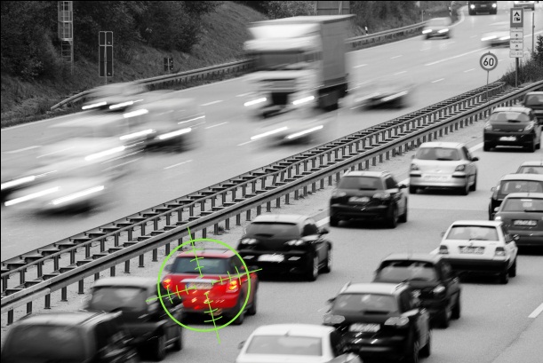
Figure 52. Suspected Vehicle
CityMIND tracks vehicles that are of interest to security and safety personnel. The system can detect vehicles automatically, using License Plate Recognition (LPR) equipment, or manually by the CityMIND Operator who monitors the cameras − the operator creates a manual event if he sees a suspicious vehicle.
Vehicle details are stored and updated in the red lists and white lists. These vehicles can later be linked to other CityMIND objects and events.
- Red List stores information on suspicious vehicles.
- White List vehicles do not create Events. These are vehicles belonging to safety and security organizations, diplomats, or other authorities, and are allowed free movement, without raising suspicion.
To define a new vehicle, perform the following:
- In the video screen, select a tile with Video, select Tile sub-tab and click Snapshot 🡺 Create Suspect Vehicle.
Figure 53. Create Suspected Person
Note: A person can also be created from the Suspect tab 🡺 Red List drop-down list 🡺 Red List sub-tab 🡺 New Vehicle icon,
Or, from the Home tab, under New Items. Make sure that a vehicle list is already created.
Note: The image of the new vehicle object is taken as a snapshot of the video in the tile.
Figure 54. Red List Tab in the Data Screen
- You can also create a vehicle in the Red List window, which displays three primary panes:
- Lists pane groups all the defined vehicles
- Vehicles List grid lists the vehicles in the selected group, with their basic details.
- Vehicle Details shows the specific details of the vehicles selected in the Vehicles List pane.
- In the tool ribbon, go to the Objects group and click the New Vehicle icon ().
The New Vehicle dialog box opens, showing all the relevant information.
Figure 55. New Vehicle Dialog Box
- Enter the following information into the relevant fields:
Table 6. New Vehicle Dialog Box Fields
|
Field |
Details |
|
List |
If you are not creating a vehicle from a list, then you need to select an existing list to add the vehicle to, or create a new one. |
|
Pictures |
If a picture of the vehicle is available, click the Add Picture icon |
|
Plate |
|
|
Country |
From the drop-down list, select the license plate country. |
|
Plate Type |
From the drop-down list, select the license plate type. |
|
Plate # |
Type the vehicle’s license plate number. |
|
Code |
License plate prefix. |
|
General |
|
|
Car Make |
From the drop-down list, select the vehicle brand. |
|
Model |
From the drop-down list, select the vehicle model. |
|
Class |
Choose the class from the drop-down menu. |
|
Color |
From the drop-down list, select the vehicle color. |
|
Year |
Type the year in which the vehicle was manufactured. |
|
Special Markings |
Type free text of physical information that may assist in identifying the vehicle. |
|
Related Objects |
Add related objects to the vehicle. |
- Click the Save and Close icon () to save the new vehicle and close the dialog box.
Note: You can also create a vehicle in the Red List window, which displays three primary panes:
- Lists pane shows the defined vehicles
- Vehicles List grid lists the vehicles in the selected group, with their basic details
- Vehicle Details shows the specific details of the vehicles selected in the Vehicles List pane.
To create the vehicle, in the tool ribbon, go to the Objects group and click the New Vehicle icon (![]() ).
).
To edit a vehicle, perform the following:
- Click the Suspects tab and select Red List or White List in the drop-down list.
- Click the Red List or White List sub-tab.
- In the Lists pane, select a list of vehicles.
The grid in the middle pane shows the vehicles in the list.
- Select a specific vehicle in the grid.
- Click the Open Kit icon ().
The vehicle Details window opens.
- Make the required changes to the vehicle; then, click the Save and Close icon ().
To delete a vehicle, perform the following:
Note: An Operator cannot delete a vehicle that is related to other objects, he first needs to remove those connections.
- Click the Suspects tab and select Red List or White List in the drop-down list.
- Click the Red List or White List sub-tab.
- In the Lists pane, select a list of vehicles.
The grid in the middle pane shows the vehicles in the list.
- Select a specific vehicle in the grid.
- Click the Delete Vehicle icon ().
The vehicle is deleted from the list.
The Investigator may notice a vehicle that is involved in suspicious activity. This vehicle may be spotted, so that detections from LPR sensors in the monitored urban will trigger events when locating the vehicle. This is done by creating an instant rule in the system. The rule requires significant system resources, and therefore it expires after a predefined period of time. The rule also expires when the user who created it logs out of the system.
To Spot a Vehicle:
- In any CityMIND screen, click the Home tab.
- Click the Spot Vehicle icon ().
The Create Spot Vehicle dialog box appears.
Figure 56. Create Spot Vehicle Quick Rule
- Click the Country drop-down list and select the license plate country.
- Click the Plate Type drop-down list and select the license plate type.
- Optionally, In the Code field, enter additional codes, such as license plate prefix.
- Choose the registration number matching method:
- Exact Match – an alert will be created upon exact match of the spotted license plate with what you entered
- Contain – an alert will be generated when the license plate of a vehicle contains the string that you entered anywhere in its license plate
- Includes – an alert will be generated if the license plate includes the string you entered but not necessarily in the exact sequence
- Enter the time interval during which you want the spotting will be active. The rule can run between 1 -12 hours. The default is 2 hours.
Notes:
- Upon reaching the time interval, the rule is automatically deactivated, and removed from the Rules grid.
- The rule is associated with the user who created it. Upon log out, the rule is automatically removed.
- Click Save to save the vehicle definition and close the dialog box.
This section explains how to create polygons on the USAP screen for Sites, Rules and Tasks. When creating a site or a task, an Operator has the option of defining the location as a polygon. A polygon is a shape that you draw on the map to mark an area of significance, such as the location of a car bombing site.
To Create a Polygon, perform the following:
- From a site or task that you can edit, click Polygon.
Note: The Add Location icon () is located in the General pane for Sites, and in the Task Details pane for Tasks.
- Navigate to the desired location in the USAP map window and click each point of a polygon that encompasses the site.
Figure 57. Defining a Location by Polygon
- A red polygon appears on the map with every point that you click.
- Double-click the last point of the polygon to close it.
- Click the Save and Close icon () to save the new locations.
Each tab in the video screen is also called a page. By default there are four tiles on each page, but the Operator can choose a different layout from the options in the Layout sub-tab.
The Operator can display different pages with a predefined layout. When accepting an automatic Event a new page opens with the video clip for that event. Up to 3 cameras, live and playback, that show what happened, and if the Event is still ongoing. If there are 3 cameras available, the tile layout is 3X2.
Operators can create a page with a specific layout and cameras, and then save the page, for future use. Whenever that page is displayed the selected cameras automatically open and show live video in the selected layout.
To create a page, perform the following:
- In the tabs, select the + tab to open a new page.
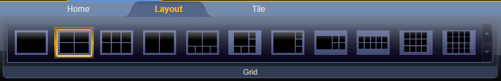
- In the Layout sub-tab, select the desired layout.
- Open cameras on empty tiles (see Figure 58, page 91).
- From the Layout sub-tab of the tool ribbon, in the Pages group, type the name of the page in the drop-down list; then, click the Save
( ) icon.
The page is now saved into the system.
To open a saved page, perform the following:
- From the Layout sub-tab of the tool ribbon, in the Pages group, select the page from the drop-down list; then, click the Display (
 ) icon.
To delete a page, perform the following:
- From the Layout sub-tab of the tool ribbon, in the Pages group, select the page from the drop-down list; then, click the Delete (
 ) icon.
A tour is a sequence of cameras that is displayed in one video tile. A tour is a useful way to allow Operators to monitor an area from all angles, without having to manually switch cameras. Operators can customize the duration of each camera, add and remove cameras, and reorganize the order of cameras as necessary.
Tours are managed from the Manage Tours window.
To open the Manage Tours window, perform the following:
- Right-click one of the tiles, and select Tours.
Or, from the Layout sub-tab of the tool ribbon, click the Select Tours (![]() ) icon.
) icon.
The Manage Tours window opens.
Figure 61. Manage Tours Window
Selecting a tour from the grid enables you to see a preview of the tour at the bottom of the window.
This section explains how to add a tour. Tours are added from the tour editor window, where they can also be viewed and deleted.
To add a tour, perform the following:
- In the tool ribbon of the Manage Tours window, click the Add () icon.
The Tour Editor window opens
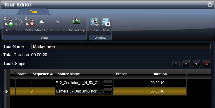
- In the Tour Name field, enter a name for the tour.
- If you want to add a camera, perform the following:
- In the tool ribbon, click the Add () icon,
A new row is added to the grid.
- In the Source Name column, click the browse () icon.
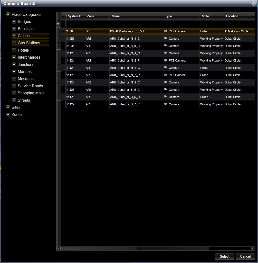
Figure 63. Camera Search Window
- In the left pane, select the zone, site, or street, where the camera is located.
The cameras in that location appear in the grid.
- Select a camera from the grid, and click Select.
The Camera Search window closes, and the camera is now added to the row in the Tour Editor window.
- Repeat this procedure for each camera you want to add.
- If the camera you have added is a PTZ Camera, then in the Preset column, select a preset position from the drop-down list.
- In the Duration column, type the amount of time the camera should play.
Note: By default the duration is 10 seconds. You can adjust this in increments of 10 seconds.
- Repeat steps 3-5 for each camera you want to add.
Note: A camera can appear more than once in a Tour. This is useful in PTZ cameras, when you want to view more than one FOV by the same camera.
- If you want the tour to run in a constant loop, in the tool ribbon, click the Run in Loop () icon.
- You can reorganize the order of cameras by clicking the up
() and down () arrows in the tool ribbon. - To save the tour, click the Save () icon.
- To close the tour, click the Close () icon.
Operators edit tours from the Tour Manager, to add, remove or reorganize cameras, or to change their duration.
To edit a tour, perform the following:
- In the Manage Tours window, select a tour to edit.
- In the tool ribbon, click the View icon ().
The Tour Editor window opens (see Figure 62, page 97).
- To edit the tour, in the tool ribbon, click the Edit () icon.
- Make the changes to the tour.
- To save the tour, click the Save () icon.
- To close the tour, click the Close () icon.
Operators with the proper authorizations can delete tours from the system.
To delete a tour, perform the following:
- In the Manage Tours window, select a tour to delete.
- In the tool ribbon, click the Delete icon ().
A confirmation message appears.
- To delete the tour, click Yes.
Tours are played from the Manage Tours window.
The table below lists the different functions for controlling a tour.
|
Icon |
Item |
Description |
|
|
Play |
Begin playing the Tour |
|
|
Pause |
Pause the tour |
|
|
Resume |
Resume playing the tour |
|
|
Go to next step |
Go to the next camera in the tour |
|
|
Go to previous step |
Go to the previous camera in the tour |
|
|
Go to step |
Go to a specific camera in the tour |
|
|
Abort |
Abort playing the tour |
Figure 64. Video Screen with Timeline
The video timeline shows the time span of a recorded video. It shows the entire time a video was recorded from the selected camera. The operator can either view live video from the camera, or playback of a video that was previously recorded and saved.
Note: The system saves recorded video streams for thirty (30) days, providing enough time to investigate recent events.
The timeline shows the following information:
Table 8. Timeline Features
|
Icon |
Item |
Description |
|
|
Viewing Time Frame |
Adjustable frame within recorded time period, showing the period of time that is shown in the detailed time line. |
|
|
Detailed Timeline |
Detailed timeline showing all bookmarks and current frame within recorded period. |
|
|
Currently Viewed Frame |
Shows the point along the timeline that appears in the highlighted tile. |
|
|
Bookmark |
Shows the point along the timeline when each bookmark was designated. |
|
|
Current Frame |
Shows the numerical value for the current frame in the timeline, and the speed at which the video stream is being shown. |
|
Timeline Toolbar |
||
|
|
Play/Pause |
Click to play or pause active video recording. |
|
|
Rewind One Frame |
Rewind the recorded video one frame at a time |
|
|
Slow Rewind |
Rewind recorded video slowly |
|
|
Rewind |
Rewind recorded video at normal speed |
|
|
Forward |
Play recorded video forward at normal speed. |
|
|
Slow Forward |
Play recorded video forward at slow speed. |
|
|
Forward One Frame |
Forward the recorded video one frame at a time |
|
|
Add Bookmark |
Bookmark the current frame. |
|
|
Next Bookmark |
Forward to the next bookmark. |
|
|
Previous Bookmark |
Rewind to the previous bookmark. |
|
|
Show Bookmark |
Show bookmark name |
|
|
Capture Frame |
Save the current frame as a still image. |
The timeline enables the operator to navigate through a recorded video, locating and bookmarking important events, and saving still images.
Bookmarks are pointers that you create to specific times in a video clip from a camera. You can later query each bookmark for various uses, such as attaching it to a relevant Event.
This section explains how to create bookmarks in live or recorded video clips that are open on the Video screen.
To Create a Bookmark, perform the following:
Figure 65. Add Bookmark Icon
- In the Video Screen, select a tile showing the requested footage (live or playback) from a camera, and at the bottom left corner, click the icon.
The Add Bookmark dialog box appears.
- Enter a description of the bookmark, and click Save.
This section explains how to create snapshots from live and playback videos.
To Create Snapshots, perform the following:
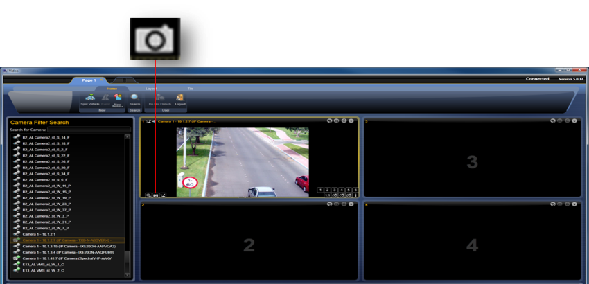
Figure 66. Video Screen – Camera Icon
- In the Video screen, on a tile with an open camera (live or playback), click the Camera icon.
A snapshot of the moment is saved to C:\exports
The CityMIND windows are integrated so that events, objects and cameras can be located on the USAP map. The Locate feature enables the Operator to locate the geographic location of a camera on the USAP map.
To Locate a Camera, perform the following:
- In the Video screen, open the camera and click the tile where the camera stream appears.
- Click the Tile sub-tab.
- In the Camera area, click the Locate Camera icon ().
The USAP map centers on the location of the camera.
Figure 67. Video Screen – Locate Camera
To Locate an Event, perform the following:
- Go to the Data window, click the Events tab and Events sub-tab.
- In the Events pane, click on an event.
- In the View area, click the Locate icon ().
The USAP map centers on the location of the event.
Layers enable the CityMIND Operators to organize the information in the system into a manageable format. CityMIND uses the USAP screen to show all the information gathered by the system. The many events and objects that a system Operator can view can be overwhelming and confusing to the system Operators. Organizing this information into layers assists the Shift Manager and Administrator in dividing entities, such as events and objects according to zones, categories and Operators. This enables individual operators and investigators to view only the information that is relevant to them during their current shift.
The Layers can be accessed through the Public Layers pane on the USAP screen. The Public Layers pane lists all the defined layers and the element types that compose each layer, such as events, sites, and cameras. For example, selecting to show Zones causes the map to show the zone borders and numbers. Selecting to show Cameras causes the map to show the location and view angles of all the cameras. Clicking a layer in the pane also causes the data pane to list all the elements and objects in that layer.
The Sensors pane lists all the sites, streets, junctions and zones in the urban environment. Selecting the check box next to each zone causes the 2D/3D map to show the sensors in that zone. Clicking a zone in the pane causes the data pane to list all the sensors in that zone, with additional basic information, such as sensor ID, sensor name, location coordinates and state.
CityMIND categorizes layers as Static or Dynamic.
- Static layers show only the Events, Tasks, Sites and sensors that were open when the layer was set to Static.
- Dynamic layers update the situation to show new Events, Tasks, Sites and sensors as they are created or changed, manually or automatically.
When an operator begins his shift, he is assigned tasks and zones by the Shift Manager. Each zone includes open events that were created manually or automatically, along with tasks that are to be performed in the designated zone (viewing cameras within the zone), and objects that are relevant to the zone (sites, people and vehicles in the zone). The operator can use layers to limit his view in the USAP screen to show only the zones and entities like events and objects relevant to his tasks and shift.
The USAP layers are categorized into the following groups:
- GIS Layers: Layer definitions that were imported from external data, such as maps of roads or models of important buildings.
- System Layers: Zones and objects, such as sites, and events.
- User Defined Layers: Operators can define custom static and dynamic layers. The user-defined dynamic layers enable the Operator to be continuously updated on events and tasks during his shift.
- Sensors: Location and position of cameras, LPRs, and tamper detectors. All the sensors can be located according to zones, defined sites, streets and junctions.
To show or hide a particular layer, select or clear the selection of the check box next to each layer name. Right-clicking an object centralizes it in the USAP window.
When the operator is notified of an event that may be automatic or manual, he may want to collect information from different sensors that cover the same location. The Show Covering Sensors feature enables the Operator to find all the sensors that cover a specified location or are in the vicinity.
To Show Covering Sensors, perform the following:
- Go to the USAP window and right-click on the USAP map.
Figure 68. USAP Right-Click Drop-Down List
A drop-down list opens.
- Select Show Covering Sensors.
The USAP map shows various objects, such as sites and cameras, in their location. The operator can open the recorded video stream from a camera that he selects on the USAP map.
To Show Video from a Camera on the USAP Map, perform the following:
- Go to the USAP window and locate a camera.
- Right-click the camera icon and select one of the following from the drop-down list:
- Show Live
- Show Instant Replay
- Show Playback
- Go to the Video screen, and view the selected camera’s video stream in one of the camera tiles.
The Locate on Map feature enables the operator to find the geographical location of entities such as: zone, defined site, or sensor.
To Locate on Map a geographical location, perform the following:
- Go to the USAP window.
- At the top of the left pane, the Locate on Map area, click the down arrow (▼), opening the search fields.
- Click the top field, opening a drop-down list of objects that can be searched.
Figure 69. Locate on Map Drop-Down List
- Select an entity type to search, such as Sensor, Zone, Placemarks or Sites.
- In the field below, enter the search parameter, such as the entity name.
Note: As you type the object name, the entities that match the type and the name appear in a list below.
Figure 70. Locate on Map Search Results
- In the list that appears, click a location.
The USAP map focuses on the location of the entity or entered coordinates.
Note: If the search parameter is Coordinates, enter the map coordinates in the N and E fields, and click the Locate on Map icon.
Figure 71. Axis Joystick
Users can use a joystick to control PTZ cameras in order to move the camera left, right, up and down, and to zoom in and zoom out.
To move the camera: Move stick in the desired direction.
To zoom in/out: Turn joystick clockwise to zoom in and anticlockwise to zoom out.
Preset: Press J1 for Home Position and J2 / J3 / J4 / R for preset 2 to 5.
Maximum zoom out [1:1]: Press L.
![]() Note: The joystick can also be activated by clicking the Joystick is inactive ( ) icon, on the Tile sub-tab.
Note: The joystick can also be activated by clicking the Joystick is inactive ( ) icon, on the Tile sub-tab.
Users also can use a joystick to control USAP in order to move the map left, right, up and down, and to zoom in and zoom out.
To move the map: Move stick in the desired direction.
To zoom in/out: Turn joystick clockwise to zoom in and anticlockwise to zoom out.
Change view: Press J1 to lower the view (closer to ground) and J4 to higher the view (closer to sky).
Rotate: Press L to rotate map left and R to rotate map right.
![]() Note: The joystick can also be activated by clicking the Joystick is inactive ( ) icon, on the Tile sub-tab.
Note: The joystick can also be activated by clicking the Joystick is inactive ( ) icon, on the Tile sub-tab.
When an urgent event or task occurs, the Shift Manager may have to assign it to an operator who is already assigned zones. While the operator is handling the urgent event or task, other automatic events are generated in the zones that he has been assigned. This may divert his attention from the primary urgent event.
The operator can temporarily block incoming automatic events by activating the Do Not Disturb feature. This feature prevents new events from popping up in his display.
To activate Do Not Disturb, perform the following:
- In any window, click the Home sub-tab.
- In the User area, click the Do Not Disturb icon ().
- To exit this feature and return to receiving all events, click the Exit Do Not Disturb icon ().
Face recognition allows you to have the system actively search for a suspicious person. You can take an existing person and select to have the system actively search for that person. Whenever one of the cameras detects the person, an automatic event is created.
To have the system actively search for a person, perform the following:
- Either create a new person or edit an existing person.
- In the person’s kit in the picture verify that there is a small selected box next to the star indicating that the image is qualified for face recognition.
The top left corner may display a star. The star indicates that this image is the main image for the suspect. If the suspect has multiple images, the main image appears at the suspect grid.
The right top corner of the image may contain one of the following indicators:
- Green V symbol, indicating that the picture quality enables the suspect to be actively searched
- Yellow V symbol, indicating that the picture quality enables the suspect only to be searched via Investigation tools
- Red X symbol indicates that the picture quality is poor, and cannot be used for face recognition
Figure 72. Person Qualified for Automatic Recognition
- In the Tracking Information pane, select the Search Actively field.
- To save the person, click the Save and Close icon ().
Whenever a camera detects that person, an automatic Suspicious Person Event is triggered, and a pop-up appears.
Figure 73. Suspicious Person Event
For more information on handling automatic events, see section 5.1, page 30.
The Instant Messaging tool enables the user to communicate with other users, from the same or other agencies, in real time, via text messages and voice calls from the messenger.
To send an instant message:
- Activate the Instant Messaging by clicking the IM icon in the main toolbar. The icon is available on all three screens. The IM window will open on the screen in which you clicked the icon.
Note: The IM icon is available if the operator was granted permissions by the administrator.
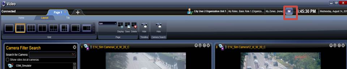
Figure 74. Instant Messaging Button
- In the IM tool that opens, from the Contacts pane, choose a contact from the contact list upon public groups that are defined in the Active Directory.
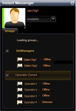
Figure 75. Instant Messaging
- In the IM tool that opens, from the Contacts pane, choose a contact from the contact list that appears upon the public groups that are defined for you in the Active Directory.
- Double-click the contact, and if he is available, type your text message.
To start a call from the messenger:
- Repeat step 1-2 in the previous procedure.
- When the contact list opens, upon mouse hover, you will be offered the opportunity to call the contacts that are currently online.
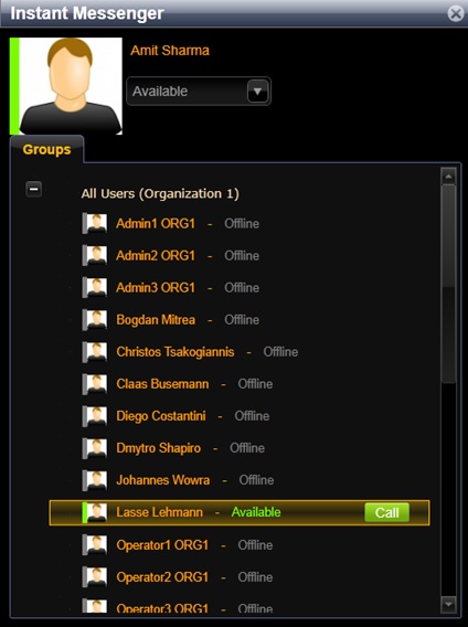
Figure 76. Instant Messaging Call
- Click the Call button to initiate a call via the IM tool. You can call one contact at a time.
- If the person you are calling to chooses to accept the call, the call conversation will take place. You can use the computer’s headphone set for microphone and speaker.
- Note: You can text to the person you are calling and receive text messages from this person while you are in the call.
- To end the call, choose the Hang Up button.
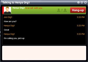
Figure 77. Instant Messaging Call Hang-Up
To receive an instant message or a call from the messenger:
- If you are listed in the Active Directory, and have permissions for instant messaging, you may be prompted that you have a call or a message.
- You can choose to accept the message or the call by clicking Accept.
Note: In case of a call you can choose to resign it.
- You can reply to the message by typing in the text box and pressing return.
- You can hang up the call by choosing Hang-up.
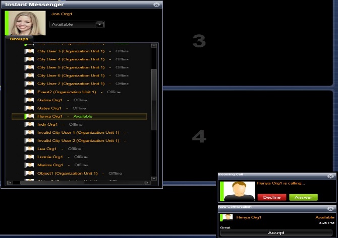
Figure 78. Accepting an Instant Call or a Message
IM Features
- If the contact is offline, a message will appear, saying the message will not be delivered.
- The instant messaging can take place in 1 on 1 mode. That is, you can chat with one user, but not with a group of users.
- The instant messaging tool supports text only.
- Instant messaging is possible with contacts from other organizations, upon granting permissions to them in their environments. Only organizations for which you have permission will spear in your contact list.
- Messaging history is saved during the session. Upon logging off, the history is deleted.
Availability Status
- You can see contact’s status in the IM page.
- The statuses Available (green) and Offline (blank) are set by the system according to the person’s actual status.
- You can set your status to Do not Disturb (red) and then turn it back to Available.
To change your status in IM:
- Activate the Instant Messaging by clicking the IM icon in the main toolbar.
Figure 79. Change Your Status in IM
CityMIND enables authorized users to broadcast messages to all other users, in a way that calls their immediate attention and requires acknowledge of message receipt. Messages can be sent to users within the organization, or to users in other organizations, depending on the broadcasting user permission level.
The broadcasted message appears as a banner at the bottom of the Data screen of the users who receive it.
When a message arrives, the bell icon at the top left corner of the user ribbon in all 3 CityMIND screen is highlighted and tilting, calling the user immediate attention to the message.
The user must confirm the message receipt by clicking the Acknowledge button at the message banner. The message stays on the Data screen until the Acknowledge button is clicked.
The bell icon is grayed out once the message is acknowledged. The user can review broadcasted messages by clicking the bell icon.
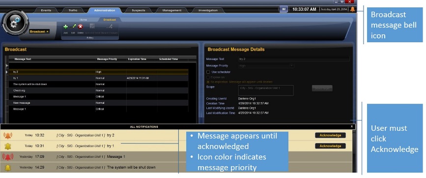
Figure 80. Message Broadcast
Message Priority
The message appears with priority indicators, colored according to their criticality. The bell icon is also colored according to criticality.
|
Priority |
Color |
Banner Icon |
Bell Icon |
|
Critical |
Red |
|
|
|
High |
Orange |
|
|
|
Normal |
Yellow |
|
|
Message Scheduling and Expiration
When broadcasting a message, the user can schedule the message to appear at a certain time. If no time is indicated, the message appears immediately after creating the message.
The User can also assign an expiration date for the message.
To broadcast a message:
- In the Administration tab, from the drop-down menu, choose Broadcast.
Note: This option is available if the operator was granted permissions by the administrator.
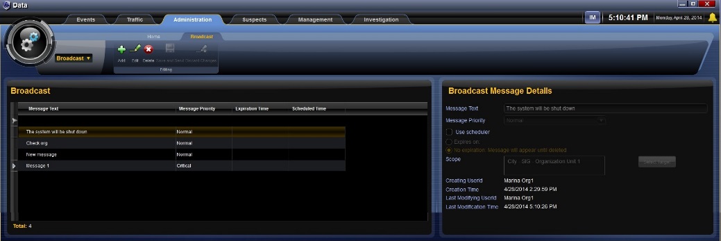
Figure 81. Starting a Broadcast Message
- To add a message, choose the Add button from the ribbon. The Broadcast Message Details pane is opened at the Details screen.
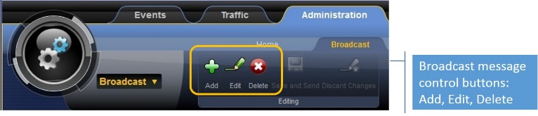
Figure 82. Broadcast Message Control Buttons
- Fill in the message details.
- Enter the message text.
- From the drop down list, choose message priority.
- Choose the scheduler if you want to send the message at a future time. If you do not set a date, the message is broadcasted immediately.
- Indicate the message expiration date.
When the message expires, it will disappear from readers’ message list. Messages with no expiration date will always appear at the readers’ message list, until they are deleted.
- If you have permissions to broadcast to users outside your organization, choose the Select Target button, and from the list that opens, choose the target audience.
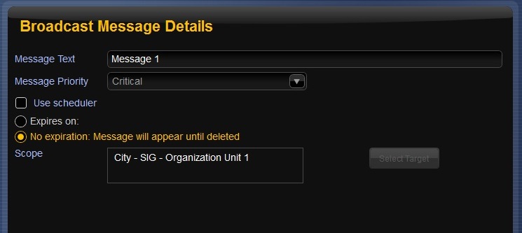
Figure 83. Broadcasting Message Details
- When your message is ready, choose the Save button to save it. The message will be broadcasted to the target audience upon your settings.
Or, choose Discard if you do not want to send the message.
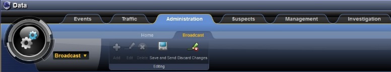
Figure 84. Saving Broadcast Message
To edit or delete a broadcasted message:
- You can edit or delete a message before it is scheduled to be delivered. To do so, in the Administration tab, from the drop-down menu, choose Broadcast. The list of the messages that you created is displayed.
- From the list, choose the message that you want to delete or edit. The message details will be displayed in the Details pane.
- To delete, choose the Delete button.
Upon deletion, the message will disappear from readers screen.
- To edit the message, in the Details pane, make the desired changes, and save.
- Receiving and Acknowledging Broadcasted Messages
Broadcasted messages may appear as banners at the bottom of all your screen. These messages are sent to you with predefined urgency level, and are intended to be read. You must acknowledge the message
To read and acknowledge a broadcasted message:
- Click the message banner that appears on the data screen.
- After reading, confirm you read the message by choosing the Acknowledge button.
Upon choosing Acknowledge, the message disappears from the Data screens.
To review acknowledged broadcasted messages:
- Choose the bell button from the top right corner of any of the CityMIND screens. The message list will appear in the Data screen.
Messages that reached their expiration date or messages that were deleted by the broadcaster will not be listed in the message grid.
Defining suspicious activity allows the Operator identify unusual behavior or appearance. Once the Operator identifies such activity, he can focus on it and track it, verifying with the Shift Manager if the activity is a reason to open an Event.
There are suspicious indicators that can be identified on a person, object or vehicle. These suspicious indicators should raise an immediate suspicion of mal-intent.
The advantage of suspicious indicators is that they facilitate focused security work because you can concentrate only on unusual people or vehicles. The disadvantages of the suspicious indicators are that there are always exceptions, and the suspicious indicators can be learned, and therefore avoided.
Following is a list of common suspicion indicators in vehicle:
- Indications of a break-in and/or tampering with the vehicle, such as: open compartments, missing/mismatched license plates or ill-fitting license plates (pasted/not matching/size)
- A vehicle parked in an odd, unusual, or suspicious manner/location and odd wires are showing
- A vehicle parked near a critical site, or unauthorized location
- A weighted down vehicle not appearing to be heavily loaded
- A person driving a vehicle in a suspicious manner
- A person driving along the road shoulder in order to avoid a gantry
- A vehicle that has undergone alterations: welding, repairs, additions and/or objects attached to the vehicle
- A person driving slowly near sensitive locations
Following is a list of common suspicious behavior patterns in people:
- A person whose presence in the area is unusual or exceptional
Figure 85. Suspicious Person in an Odd Location
- An unusual person in terms of appearance, dress and/or conduct in light of the circumstances of time and place
- Long clothing on a warm day
- Obvious Bulges underneath clothes
- Informative outfit that arouses suspicion
- Carrying an unusual bag
- No correlation between the person and the way he dresses
Figure 86. Suspicious Appearance
- A person showing unusual interest in sites or security officers and their work routine
- Photographing
- Drawing/constructing sketches
- Asking unpractical questions
- Loitering in unusual hours
Figure 87. Suspicious Interest
- Escorting parties and/or people in the vicinity appearing to be unrelated to each other but maintaining a mutual hidden contact
- Signaling
- Arriving together but entering separately or taking different cues
- Similar belongings/outfits worn by all members of the group.
Following is a list of common suspicion indicators in objects:
- An object/mean (luggage/vehicle) that does not match a person’s appearance
- An object appearing in an unusual location/place (suitcase under a bridge)
Figure 88. Suspicious Objects
C-React (The CityMind Mobile Application) is an application that runs on an Android-based tablet and allows mobile responders in police cars to:
- Communicate with the servers in the CityMind data center.
- Send current updates of their positioning information.
- Share events and other operational information with operators in the C&C center.
In addition, Shift Managers in the C&C center or in a local police station will be able to view the current positions of the police cars and send them messages containing the details of events they will be expected to handle.
To log into the Mobile Application, perform the following steps:
- On the tablet, tap the icon shown below to launch the Mobile Application.
- The Mobile Application’s Login window opens.
Figure 89. C-React Login Window
- In the Login window, enter a user name and password.
- Tap Login. The C-React window opens.
Figure 90. C-React Application
- Log out of C-React Application
To log out of C-React Application, tap the Menu button on the frame of the tablet and select Logout.
- C-React Application Window
The C-React Application window consists of a map, an event list, and a toolbar.
- Map - The C-React Application map is a 2D representation of the protected site. The map shows the current location of the mobile responder.
- Event List - The event list shows all events currently assigned to this mobile responder.
- Toolbar - The toolbar provides tools to enable the mobile responder to initiate an investigation, create an event (report), and issue an SOS.
Mobile responders can use the C-React Application’s report function to create events and send them to the C&C center. To create an event, perform the following steps:
- In the toolbar, tap the Report icon shown below:
- The Create New Report window opens.
Figure 91. Create New Report Window
- In the Category pane at the top of the window, tap the More Categories icon and select an incident type.
- In the Severity pane, tap a severity to select it. The options are:
- Critical
- Major
- Minor
- Warning
- In the Content pane, do the following:
- In the Text column, enter a brief description of the incident using the tablet’s virtual keyboard.
- In the Attach Photo column, attach a photo of the incident if possible. There are two ways to do this:
- To take a photograph of the incident using the tablet’s camera, tap Attach Photo, and select Take a photo. Then, take the photograph using the tablet’s camera. A thumbnail of the photograph will appear in the Content pane.
- To use an existing photograph, tap Attach Photo and select Choose existing. Then, locate the photograph. A thumbnail of the photograph will appear in the Content pane.
- When finished, tap the Send button. The report of the event is sent to the C&C center and the appropriate mobile responder.
A vehicle investigation allows a mobile responder to search for a specific vehicle, based on the vehicle’s license plate number or other information. To initiate a vehicle investigation, perform the following steps:
- In the toolbar, tap the Investigate icon shown below:
- The Investigate window opens.
Figure 92. Investigation Window
- If you know the vehicle’s license plate number and want to obtain additional details about the vehicle, do the following:
- Tap Get Vehicle Details. A License Number field opens.
Figure 93. License Number Field
- Enter the license plate number of the vehicle.
- Tap Get Details. The system displays about the vehicle and its owner.
- If you know the date and location of an incident involving the vehicle, do the following:
- Tap Search for Vehicles. The system displays a number of fields to identify the vehicle.
Figure 94. License Plate Search Fields
- The Date/Time field defaults to Last 1 hour. To change this, tap the field to select a different time. The options are:
- Last 2 hours
- Last 3 hours
- Last 4 hours
- Enter a specific date and time
- The Location field defaults to the current location. To change the location, tap the Location icon below and then click on the correct location on the map of the site that is displayed.
Note: The Date/Time and Location fields are required. The remaining fields are optional.
- If you know any of the characters in the vehicle’s license plate number, enter them in the Partial License No field.
- If you know the make of the vehicle, select it from the drop-down list in the Make field.
- If you know the color of the vehicle, select it from the drop-down list in the Color field.
- When finished, tap Search. The results of the search are displayed.
A suspect investigation allows a mobile responder to search for a specific suspect, based on the suspect’s picture taken live from the scene. To initiate a suspect investigation, perform the following steps:
- In the toolbar, tap the Investigate icon shown below:
- The Investigate window opens.
Figure 95. Investigation Window
- Tap the picture area or select a photo.
Figure 96. People Investigation
- Press Search Suspect button.
Figure 97. Suspect Search Results
An SOS message allows a mobile responder to request assistance from the C&C center quickly. It is generally used when there is not enough time to enter an event. To send an SOS, click the SOS icon shown below:
C-Share application is a global emergency services which allows the citizens to report directly to emergency serveries and municipalities agencies.
C-Share application protect yourself, your neighbors and public safety by sending public report from any location and help city assets to get more information about city incidents and response in more efficient way.
Using the application user can do the following:
- Send SOS Message using SOS Button
- Send Event Message
- Call police
- Get message from municipality
- Review last message
- CAD (911)
911 is Fiscalía emergency services which receive calls from citizens which report directly to emergency serveries and municipalities agencies.
Once emergency call received in 911, event is creating in 911 system and called by CityMind system.
Upon receiving 911 event in CityMind system, an event is created in CityMind system with all relevant information.
- OSINT
Open Source Intelligence (OSINT) is data collected from publicly available sources to be used in an intelligence context. In CityMind terms, OSINT uses for enriching suspects or enriching investigation cases by requests made by an investigator.
Suspect social enrichment feature allows user to get data from the internet regarding a specific suspect in the system.
Data enrichment contains names, gender, phone numbers, addresses, email addresses, social networks accounts, images and connected people.
Investigation feature allows investigator running queries for system detections and saving artifacts with comments, significance and reports.
Similarly, OSINT investigation allows the user to request for OSINT data from the web within an investigation case.
An OSINT request made by a CityMind user is sent outside of the system to an analyst.
Analyst then starts collecting and analyzing data based on the request description. When analyst finishes working on the request, CityMind user can refresh the OSINT request within the investigation case, get the insights and reports made by the analyst and continue investigating within CityMind system.
Created with the Personal Edition of HelpNDoc: Easily create HTML Help documents